|
[B] Engine
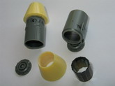
Compressor Fan
Compressor bullet is
too pointed, replacement shaped from scrap resin. Using masking tape over the
blades when sanding, the detail is not damaged.
Click on
image below to see larger image
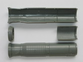
Since the engine
body will not be seen, I removed the middle section, so as to finish the intakes
and jet pipes separately. It also allowed fitting JPs later, rather before
fuselage closure.
Click on
image below to see larger image
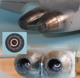
[C] Jet
Pipes & Nozzles
I have used the BB nozzles, but the detail is improved by using Eduard PE,
sanding inside of nozzles until PE fitted. I bent the polygon shape by making a
small template. A 12-sided polygon was drawn to size on paper, and a piece of
resin shaped to the internal angle. Each section bent using this angle template.
The flame holder ring was reduced in depth, as it seems too deep. Jet pipes
fitted when fuselage finished.
Click on
images below to see larger images
PAINTING:
Turbine - Outer section. Citadel Boltgun metal, then HS216 Rust (thinned
1: 5) to raised areas. Brushed with enamel thinners to ‘thin-out’. Dry
brushed grey and brown pastels (Grey14 and BE12).
- Inner cone and blades. Citadel Bone, then Citadel Tin Bitz to cone and
HS126 Rust
(thinned 1: 5) to turbine blades as above. Dry brushed brown and white
pastels and
Hu33 (thinned).
- Inner Ring Tamiya XF2
- Outer Ring Hu64
Jet Pipe and inside petals. Sprayed with Citadel Bone. Applied streaks of
HS126 Rust(thinned 1: 5) and Hu33 (thinned 1:4) by brush, then
thinners/brush to effect. Sealed, then white pastel wash to rear (aft) and
dark grey pastel wash to front of jet pipes.
The 4 rows of holes/fasteners(?) to the inside petals were simulated using
black decal dots. Cut using 0.6mm ID s/steel tubing. Rows 3 & 4
positioned by 5.5mm width of Tamiya tape at front of BB nozzle to position
row 4; then ~1mm(by eye) aft for row 3. Rows 2 & 1 positioned using a
2.5mm width of Tamiya tape set 5.5mm in from the rear of the nozzles, the
dots positioned at either side of the 2.5mm tape. Sealed ‘dots’ with
gloss acrylic before pastel ‘washes’. Blank ‘taped’ all petals,
sprayed Alclad jet exhaust, removed random blanks and re-sprayed, then
removed all blanks and lightly sprayed to effect. Sprayed matt acrylic
(Future: flat base, 4: 1)
Outside Petals. Alclad stainless steel over gloss black enamel. Masked
‘collar’ and lightly sprayed with Alclad jet exhaust. Removed masking
to ‘collar’ and lightly sprayed with Alclad jet exhaust to effect.
Acrylic gloss coated then applied matt black (HU33) to ‘lines’ by
brush. After drying, excess paint removed with tissue, barely wetted with
enamel thinners. Sprayed Hu33 to effect, sealed with satin acrylic.
Click on
image below to see larger image
PART 3: REAR
FUSELAGE, WINGS and FINS
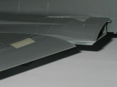
[A] Wings
The LEs are not straight, which seems to be a common problem. You need to get
them straight during cementing (solvent, not cyano) and not afterwards. Did this
by first gluing LE ONLY, securing in a ‘jig’. Can be 2 pieces of plastic,
wood etc set converging to nip ‘false’ LE when secured in jig with masking
tape. After drying overnight, glued TE.
Click on
image below to see larger image
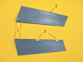
[B] Leading edge
flaps.
To set them at the characteristic droop, it has been suggested you just cut off
the wing ‘false’ LE and remove 2mm* from the bottom section of the flap.
This does not work. As you lower the flap, the thickness increases. Also, I do
not want to remove wing ‘false’ LE having just got the wings straight!
I found vernier callipers a must for this modification. In order to get the
flaps to droop, first needed to reduce the width (plan view) of the ‘false’
LEs on wings, to 3.5mm inboard and 1.2mm outboard. Then I scraped the top of the
wing ‘false’ LE with a SM No.10 blade, until it was almost triangular in
cross-section. Otherwise the top rounded LE ‘pushes’ the flap surface above
the wing. The LE flaps were then reduced in thickness as follows:
Click on
image below to see larger image
A= Top surface; B=
lower surface
Removed 1.0-1.2mm from the TE of the lower section B by sanding. It is vital to
check A and B when together are parallel on the back edge, otherwise they are
not going to fit the wing properly. If you remove 2mm as suggested*, the flaps
droop too much I think! Although these flaps can go down to 30°, they don’t
seem anything like that when aircraft is parked.
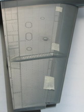
#1 Longitudinal trailing edge/spar detail (long red lines) was removed from A
and B, leaving the lateral ‘ribs’.
#2 A new ‘false’ spar ( 2 pieces) was formed from 0.5mm card (oversized
tapered strip 4mm to 1.5mm), set in 6.5mm at inboard and 3mm at outboard. File
(round) lateral ribs to match new spar position.
#3 Sand progressively on new spar and lateral ribs (marked short red lines) with
constant checking of combined thickness (temp hold with tape) at 3 points along
length (inboard, wing split and outboard) until flap thickness matches wing at
drooped position.
Inboard/outboard flap sections separated when completed.
Click on
images below to see larger images
Fixing L.E. Flaps
These were ‘dropped’ a little more than originally proposed. Using masking
tape to protect top edge, more was sanded from the bottom edge. To fix you need
a ‘filler’ glue. I coarse filed some sprue and added liquid cement to
produce a thick cement paste. This takes a long time to fully set, continuing to
‘melt’ the plastic, and can produce dimples. Careful use of 5 min epoxy
would be much easier, cleaning any which comes out onto wing.
Installed port flap sections:
Click on
image below to see larger image
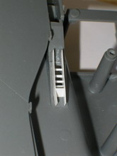
[C] Wing/fuselage
joints etc..
#1 Dry fitting the wings to the fuselage, the top panel lines do not align. I
removed the ‘U’ shaped locators on the topside, so that I could move the
wings forward about 0.5mm
#2 0.5mm card compensate filling at rear ‘spar’. Also, packed under
starboard wing at rear with 5 thou card to match top surfaces.
#3 ‘Panel lines’ filled-in for FA/18A.
#4 Filed out and constructed vents from 0.25 card.
Click on
image below to see larger image
Boundary layer air vents construction, still to be closed at base with 0.25mm
card.
Click on
images below to see larger images
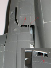
Vents outboard of
boundary layer air vent.
#1 Looking at Daco p26, this is a slot. Scribed panel line deeper, then cut
thro’ aft end with 10thou saw blade.
#2 Scale thickness is about 2” (compare stbd inset photo); reduced with needle
file and micro sanding sticks.
Click on
image below to see larger image
[D] Wing tip missile rails
Thickness of the wing extension, which is part of the missile rail (parts
D51/52), does not match the wing thickness. Also, I used the BB Exterior Set
LAU-7 rails to replace the kit ones, therefore made new wing extensions from
scrap resin pieces. Later replaced slime lights with those from Eduard exterior
set.
Click on
image below to see larger image
[E] Fins and Rudders
I preferred modifying the kit fins, having seen the Black Box replacement fins.
The kit fins have sharper detail and proved to be not too difficult to modify,
using Daco as reference.
#1 Remove details with shaped ¼” wide sanding stick and SM No.10 blade,
W&D etc
#2 Score line to extend strip at top to aid removal of ‘plate’ detail
associated with #1
#3 Structural plates from 5 thou card. The vertical strip at mid fin appears
from photos to be a structural plate rather than a panel, as kit.
#4 New antenna formed from 3.2mm rod. 2 pieces of equal length are sanded until
each is 1.2mm wide, then ‘tacked’ together (CA) to enable shaping. When
completed split to apply to fin. File at rear to receive part antenna section
from 2.5mm rod.
Removed plate detail at base of inboard fins for –A and early –C for kit
parts D7, 8, 9.
Click on
image below to see larger image
Photo below shows structural stiffener, new slime
light from 5 thou card and Eduard PE plates. It was only when I placed the
structural stiffener, that comparison with photos indicated kit slime lights
were too short. NOTE: STRUCTURAL STIFFENER SHOULD BE OUTBOARD PORT, INBOARD
STARBOARD.
Click on
image below to see larger image
Rudders.
Modifications done to improve detail and the attachment, particularly when
rudders are set at ‘deflected’ angles.
#1 Cut-outs made at base of rudders.
#2 Slots widened/deepened for hinges cut from 1.5mm square section, using a 5
thou saw blade; rounded leaving a flat side for mounting.
#3 Close-up photos do not show a panel line; filled in.
Note: Rounded LEs, as they look too angular.
Click on
image below to see larger image
Rudder used to position the centre piece of the
hinges on the fin (yet to decide angle!). For ease of alignment I reversed the
hinge layout.
Click on
image below to see larger image
[F] Rear Fuselage Construction
On completion of the intakes, the order of fit was A3/A4 side sections, then
join upper and lower fuselage. The kit instructions order of construction, I
think, will make the task more difficult.
(i) A3/A4 fit to lower fuselage and intakes.
#1 Scored lines between extremities and mid-way. Initially, some detail has to
be removed at the ends.
#2 Removed plastic, up to scored line, so as to be concave, being careful not to
go through wall. Only regular checking against fitted bay will define how much
to remove.
#3 Reduced in thickness.
Click on
image below to see larger image
Sanding was required to the fibreglass inserts
and thinning at inside front of A3/A4 to fit. My heart faltered a number of
times, but this is what it looks like after filling/sanding. Still to re-scribe
some lost detail.
Click on
image below to see larger image
#1 This edge required adjustment to get A3/A4 to
align and achieve inside fit. Set with 5 min epoxy inside and CA to edge, as
some pressure was required to get the back end to align with rear fuselage.
#2 Progressively glued from front to rear, for best fit.
Click on
image below to see larger image
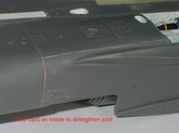
A good result may have been more difficult to
achieve, due to the use of the Aires gear bays and my intake mods!
#1 When upper and lower fuselage halves were test fitted, upper was ~1mm longer,
producing a semi-circular gap underneath, between nose and rear sections. I have
done nothing to affect overall lengths of these components!
Click on
image below to see larger image
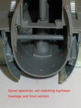
#1 With nose halves taped together and this then
taped to rear fuselage, I marked where the card infill was required.
#2 Sellotape to stop halves sticking together (haven’t finished tub yet)
#3 1mm card strips slightly oversized and super glued in place. Card sanded to
profile and thickness, with checking against rear fuselage.
Click on
image below to see larger image
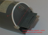
(ii) Upper & lower fuselage joining
Since card filler was required at the front end, I worked from tail to nose, so
rear was ‘square’ for nozzles. The only thing of significance was the (big)
gaps between A1 and sides A3/A4. I used a card template to check for 3
anhedral of wings when gaps were closed; used sellotape and warmed top surface
with a hair dryer.
#1 Rear fuselage slime lights, as with fins, appear to be undersized when
checked against Daco drwgs and prorata measurements. New ‘lights’ from 0.25
card.
#2 In addition to re-scribing lost panel line detail in joining, some at the
rear needed re-doing.
#3 On Scotsman’s suggestion, card was added inside to ensure best fit, minimum
filling/sanding in this area.
#4 Using Daco as ref., some panel lines were filled (yellow) and re-scribed
(red). There are corresponding ‘areas’ inboard. It is still not totally
accurate.
#5 At the outboard base of fins these ‘fillets’ seem more pronounced and are
in 4 sections; from 5 thou card. They also remove any slight gap.
#6 New pivot sleeve. I fixed pivots as instructions, but got dihedral instead of
anhedral.
NOTE: STRUCTURAL STIFFENER SHOULD BE ON STARBOARD INBOARD, NOT OUTBOARD AS
SHOWN.
John
Click on
image below to see larger image
|