|
For
those about to FLY, we salute you!
I.A.R.-80,
a Focke-Wulf or the grandpa of the Trabi?!
Why
a Focke-Wulf ?! Because the American pilots have mistaken the Romanian fighter
airplane for a Fw-190 so many times. Why the grandpa of the Trabi?! Because the
Gnome-Rhone motor of the I.A.R.-80 airplane, was eating so much oil, that even a
Trabi car looked ecological in comparison to it. (Trabi = east-German car,
actually named Trabant, well known for its rather big oil consumption).
I
confess it took me a lot of time to be ready to attack this kit. I gathered a
lot of pictures, drawings, technical data, cutaways, making lists with all the
modifications needed to be done to this kit. A good friend, who has already done
this kit, helped me with a lot of advice and suggestions. After two long years
of preparation, I considered the time was right to start working. You may see
the results below!
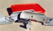
THE KIT
1/72
scale, MPM production, one injected grey plastic sprue with 30 parts, here and
there with a little flesh, fine negative panel lines (unfortunately engraved in
a wrong way), 22 resin parts not very accurate, an injection-moulded canopy not
very thick and quite clear, but again wrong in shape, PE parts for details
(buckles, instrument panel, rudder pedals and seat belts), decals include three
aces' machines. More wrong elements: landing gear bay is approximately 2mm. too
far backside, engine cowl has a too cylindrical shape and is not bulging like it
is in reality, in the back side of the cockpit the fuselage has a wrong shape,
landing gear is wrong, cockpit is too simple and the emptiness is obvious, tail
planes are wrong, aso...
|
Click on
images below to see larger images
|
|

|
 |
|
ASSEMBLING
I
began with the re-engraving of panel lines, the original ones being totally
wrong. The landing gear bay was greatly improved, but its position, relatively
2mm. too far from the leading edge, could not be corrected. This operation would
have been very complicated, implying a huge quantity of work and the results
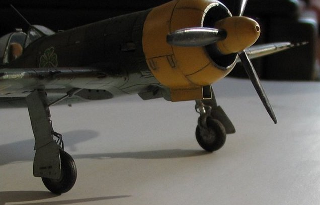
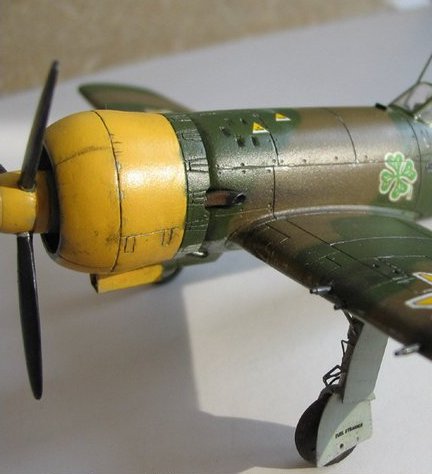
would have been unsure. So I have considered it isn’t worth doing! The engine
cowl was nevertheless restored to its proper bulging shape, by gluing a plastic
strip to it and afterwards filling the remaining space with putty. After sanding,
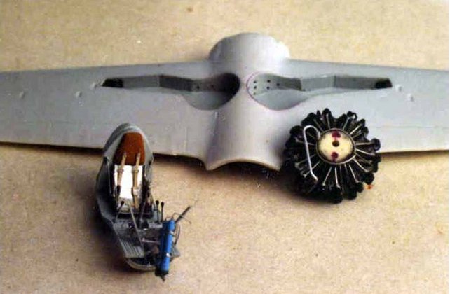
the engine cowl was re engraved as well. The engine, rather less accurately
done, with a lot of flesh, has been improved by adding: pushrods (steel wire),
spark plug wires (copper wire) and the reduction gear cooling pipe (aluminium
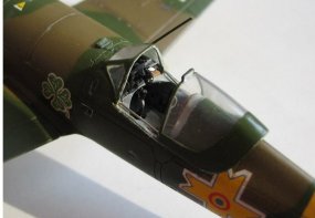
wire). The construction of the cockpit followed. The fuselage halves were painted
on the interior with light grey (Humbrol 127). I could not find out the original
colour of the interior, the general opinion swayed between grey and dirty white.
I used the same colour for the landing gear bay. The cockpit was heavily
improved. Electrical wires, the fire extinguisher, the fuse box, the fuel
hand-pump, the oxygen mask box and the hydraulic pump handle were added on its
right side.
Whereas
the oxygen tank and hose, the throttle, the DBU filter control, the landing gear
horn and electrical wires were added on the left side. I moved on to do the
cockpit floor. The following details were added: flaps and landing
gear selection levers, control stick and rudder pedals with their levers and
cables, the pilot’s seat (out of copper plate) including the headrest, seat
belts, the tail plane trim wheel, the map case, the mechanical control of the
landing gear lock and the instrument panel (landing gear retracts, flaps
hydraulic system, compressed air, brake system).
The
boards of canopy was less complex. Initially, it was cut in three pieces and
bent because the device boxes and link wires had to be glued on the back side.
The film was painted in white on the back side, where the gauges should appear,
so the device boxes had no chances to remain glued, over the film, so another
thin plastic foil had to be glued in between. The result: a sandwich pretty
thick! Next on building was the gun
sight (seven
parts!)The landing gear was remodelled, too. The upper side of the main
landing gear was cut off and replaced, by the help of Wurger, (Calin, my
friend) with a hexagonal one, as the real one was! The braced
of the pneumatic damper was made using photoetched parts. The wheel braced was
adjusted for thinning it, and on its sides the lock of the landing gear was
glued, along with the break tubes.
The
landing gear’s covers and the supports for their clamping on the main landing
gear were remade from copper plate and welded with tin. The inside reinforcements
from the landing gear covers were made by lead plate, 0.1 mm thick and glued.
The hydraulic ram
for landing gear control
was made by syringe needles, sticked one into another, and then glued together.
The landing gear and the inside of their covers were painted in the same grey as
the cockpit (Humbrol 127).
The
tail wheel was made from copper plate and wire (three parts) and painted in
aluminium (Humbrol 56).
|
Click on
images below to see larger images
|
|
|
|
|
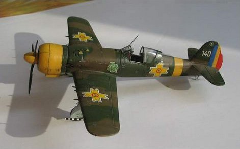
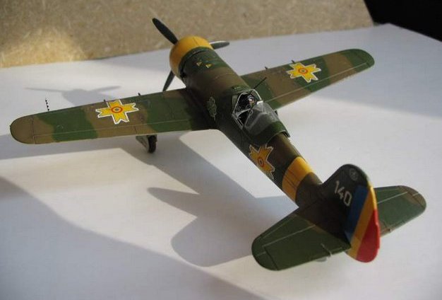
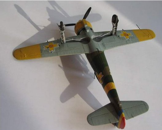
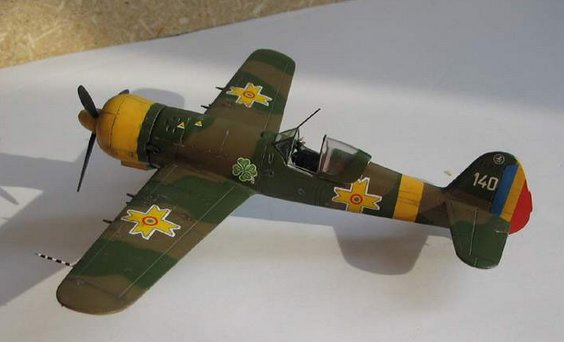
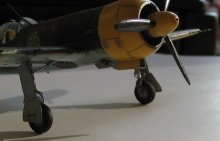
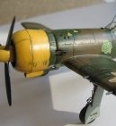
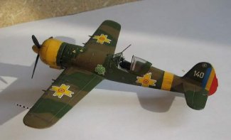
After the assembly of the fuselage was done, the shape of back “bump” was corrected, then the wings and the depth rudder were glued. The commands of the compensator were assembled on the depth rudders (the same copper plate). The final touches done (the reduction ventilation, last engravings) and the painting started. I’ve chosen the camouflage schema with the under-surface of the fuselage painted in the same colours as the upper-surface (as the factory used to paint them before the revisions and other repairs). So, the upper-surface of the wings and fuselage, along with the undersurface of the fuselage, where painted in green (MM1713) and brown
(Humbrol 142 or 3*H29+1*H155), and the under-surface of the wings and fuselage (to trailing edge of the wings) was painted in RLM 76. The engine hood, the propeller’s spinner the wingtips and the theatre marking band were painted in yellow
(Humbrol 24). The propeller’s wings were painted in Revell 9.
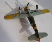
The
decals, the guns (syringe needles), the exhaust pipes (again, syringe needles,
pretty thick!), the antenna’s support and the Pitot tube were assembled. The
flag was painted on the direction. Then, the “obvious” procedures were
performed: peeling the paint, smoke, dust, oil, washing, weathering and other
“-ings”. The cockpit hood (unfortunately incorrect), was cut and assembled
open. The antenna wire was not assembled because of past experience: I’m
always ending by tripping on it.
Alexandru
- Romania
|
Click on
images below to see larger images
|
|
|
|
|
|