|
Part
1
IPMS
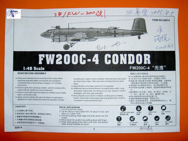
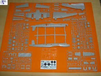
Philippines Bert Anido Chapter was blessed to have been given a test shot of a
1/48 scale Focke-Wulf Fw 200 Condor Transport/Bomber. The kit came from
none other than Trumpeter itself.
1.
At first glance, the first test shot kit arrived in the following condition:
a.
It was unboxed (all parts are wrapped in plastic)
b.
It came with a photocopied instruction sheet without the decal and
camouflage placement guide.
c.
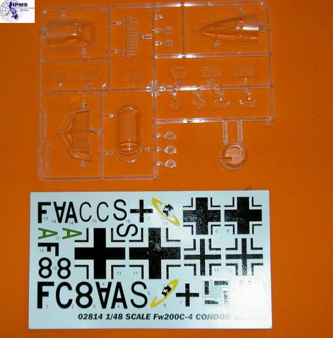
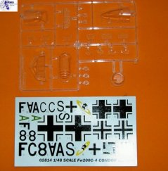
There is a decal sheet
d.
There is no (acetate) film for the instrumentation panel.
|
Click on
images below to see larger images
|
|
|
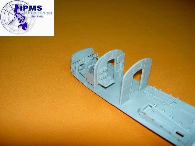
2.
Interior assemblies:
A.
Out-of-the-box observations:
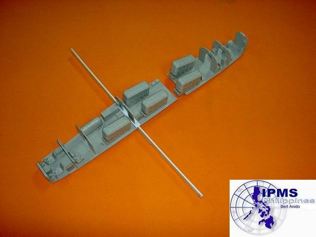
1)
The bulk of the parts make up the interior from the flight deck to the
rearmost bulkhead.
2)
The floor (thankfully!) is broken down into 3 sections which allows for
easy assembly.
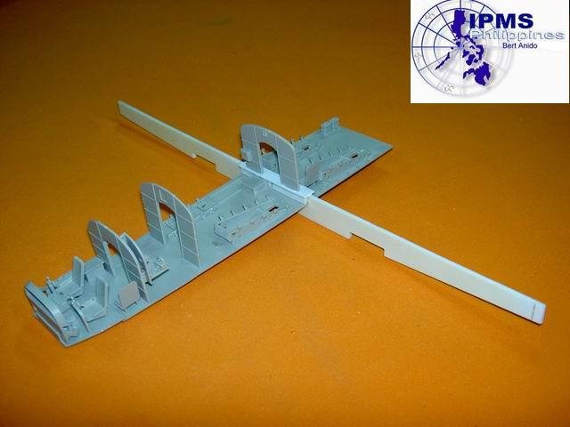
3)
Cabin lights which attach to the cabin bulkhead are molded in cleanly.
It is tempting to install lights here to illuminate the interior.
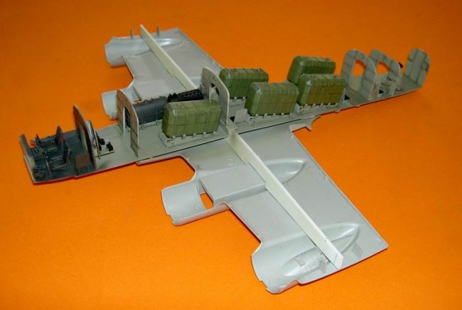
B.
Assembly:
1)
A whopping 8-step instruction with 11 sub-assemblies guide you through
the assembly of the interior.
2)
Fit is almost impeccable. The detailed parts of the interior snap
into place and are automatically aligned with their adjacent components.
a.
For example, all bulkheads, although noticeably narrower than the cabin
floor, fit so tightly that they automatically assume a perpendicular position
relative to the floor.
b.
Entire interior fits easily and neatly into the fuselage without the need
for further adjustments.
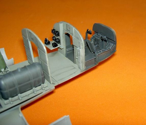
c.
“Almost Impeccable” because of the following:
1)
The pilot/co-pilot seat tabs do not conform to their locating holes on
the flight deck floor.
2)
All locating holes in the rearmost cabin floor are a tad too small for
the tabs on all the interior parts located. This is rectified by enlarging
them with a sharp knife which then snap into place in perfect alignment like the
rest of the cabin parts.
3)
Fuel cells have uneven mating surfaces, producing gaps at the seams.
4)
There are no harnesses for any of the crew seats and throttle and mixture
levels are absent as well.
5)
The rudder pedals are a bit chunky and have their toe restraining straps
molded solid. Also, mount them with a slight (2”) toe-out as the
instruction will have you install parallel to each other. (Though this is
not visible upon completion).
C.
Conclusion:
1)
Advanced out-of-the-box builders will want to add seat belts at least to
the flight deck and controls to the throttle quadrants. We can only wish
that there would be a reference for plumbing for the fuel cells made available.
2)
Lastly, for those who want to leave the rear door open, you might want to
add interior structure to the fuselage walls. The base walls are also
slightly visible through the cockpit windows and the dorsal gunner’s position.
3)
For reference to the Condor’s fuselage structure, the pilot press
limited the cutaway view published in Bombers of World War II
edited by David Donald is helpful. Also very helpful is a photo of a
Condor that crashed in Norway during World War II (www.wk2.info/karlpech.html)
3.
Wing assembly:
NOTE:
This is not the next step in the assembly sequence. The span is way past 2
ft.
A. Out-of-the-box observation
1)
Ribbing aft of the rear spar on top of the outermost flap section is only
visible in the photos found in Bombers of World War II (ibid. p. 169) in
full color, 3 views. It isn’t visible in any of the photos showing the
top with the wing in any references used.
2)
The ailerons have the overdone fabric over-rib texture on their top
surfaces only.
3)
There are sink holes on the top surface corresponding to the spar and rib
detail in the split flaps.
4)
The aileron hinge line curves at the wing tip on both the top and bottom
surfaces of the wing. The photo on p. 228 Warplanes of the Third Reich
show the top surface hinge line should be straight out to the tip while the
photo on p. 227 shows the bottom surface hinge line beginning to curve aft
outward of the outermost hinge.
|
Click on
images below to see larger images
|
 |
 |
This
indicates a Frise-type aileron which Trumpeter’s aileron airfoil did not
represent well either.
A
totally featureless wheel well boxes are provided for the nacelle interior.
Ejector
pin marks between the ribs will be hard to fill.
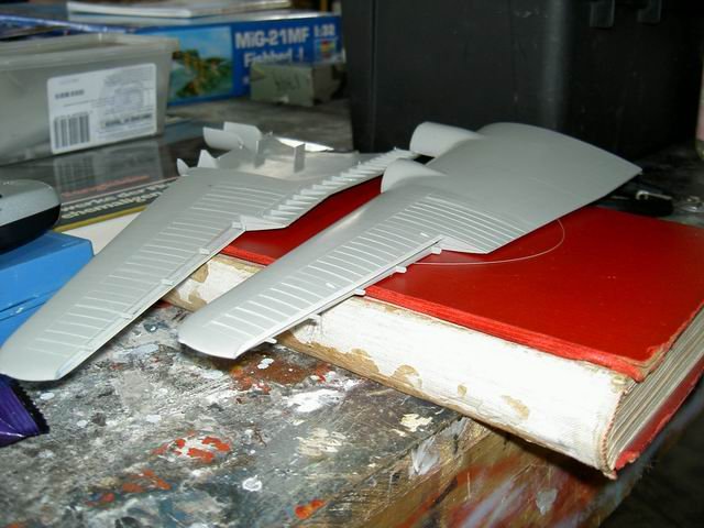
B. Assembly:
1)
Upper wing surfaces are molded with the right dihedral molded in.
Assembling the lower outer wing panels to them was straightforward with the
locating pins actually helping to align things.
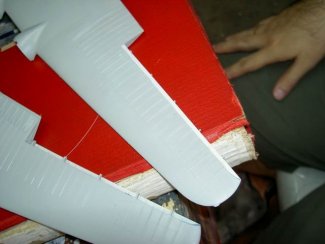
2)
Mating those assemblies to the bottom center system was easy the first
time. But due to the flimsy center section, it proved difficult the second
time around. It was obvious that the assembled wing would be grossly
flexible.
3)
In fairness (to the manufacturer and the kit), we assembled it to the
fuselage. Although the fit was excellent, the prospect of relying on the
fuselage fillet-to-wing joint, our test showed the following:
a.
When the model is picked up by the fuselage, the wing droops noticeable
and will either pull the fuselage apart or pull the wing roots apart.
b.
When put down on a flat surface, dihedral increases to a point where the
outer wheels of the landing gear lift off the table.
C.
Accuracy:
1)
As mentioned earlier, the chord of the upper wing surface upstream of the
aileron should be longer than the lower surfaces chord.
2)
The ribbing molded on the upper wing surface and the fabric above and
aluminum below treatment of the kit wing needs further research:
a.
Profile publications of the Fw 200 describes the wing: “covered with
flush-riveted stressed skin to the rear spar, the remaining fabric covered.”
b.
In p. 46 of Avions #107, February 2002 issue is the clearest
version we’ve seen of SG & KS a Fw 200 C-3 in a right bank against
gigantic white cumulus. It cleanly shows ribbing on the underside of the
outer wing panels including the ailerons. Furthermore, they appear to
begin at the front spar and not the rear spar. None of the references
mentioned changes between C-3 and C-4 wings (NOTE: This photo seems to
have been retouched where the outboard bomb pylons and the outboard engine
nacelle bomb/fuel tank releases have been edited out by a cartographer.
Enough of the ribbing detail is visible though at the outboard portion.
c.
In the Karl Pech website and www.lufthansa.ju52.de/fotos/fochefoto/foto02.htm
where a Lufthansa team of technicians seem to be retrieving a Fw 200 clearly
show the extent of aluminum-covered areas of the wing which remain covered after
all these years and that which we presume were fabric-covered. The
structures were completely bare.
D.
Conclusion:
1. In terms of structure: the wings require a spar.
a.
Trumpeter provided a carry-through structure (or at least the top of it
that protrudes above the cabin floor).
b.
Pt. C9 that is also positioned at the thickest part of the wing. We
cut 2 mm wide slots on either of its ends and cut out 2 mm wide strips from the
floor (E11) where (C9) attaches to it (refer to drawing). A wing spar was
then cut from 2 mm thick styrene sheet (see photo). This was then
installed beneath C9 and between the 2 separated sections of the floor (E11, see
photo). The cabin was temporarily attached to the lower fuselage fore and
aft then the spar glued to the inner surface of the wing flap without cement.
If any modeler would like to use this spar (drawings are provided), please take
note that the top edge is straight (in all 4 drawings available to us agree on
this) and the tops of the cut-outs for the wheel wells must be parallel to it to
ensure that all 4 main wheels touch the ground.
2.
Accuracy:
a.
Flap ribs – based on Karl Pech’s website, ribs as wing and flap ribs
should be pockmarked with lightening holes and we hope an Aftermarket outfit
will oblige the Condor fans out there.
b.
Aileron – the problem here is the airfoil section: it is molded
around while the actual section should be wedge-shaped at the leading edge (see
drawing).
c.
Fabric over-rib texture – this should extend from the main spar (3rd
span-wise engraved line from the leading edge) to the trailing edge including
the aileron and spar-wise from the 2nd rib (2nd row of
rivets) from the dihedral break until the last engraved panel line before the
wing tip. Except for the inter-rib spaces, where the teardrop-shaped
fairings are found and aileron trim tab (see drawing). Our ribs were made
from stretched sprue, half-submerged in engraved lines and cemented in place
(with liquid cement). The chord extension is from 3 mm styrene sheet.
d.
Additional access panels and skin paneling (see drawing) – they
are in no way complete or 100% accurate but are merely derived from various
close-ups of the engine nacelles and Karl Pech’s aircraft. We feel
compelled to add them from 3 mm styrene sheet as some of them are very
important! The inboard ones being refueling access panels for the wing
fuel tanks.
4.
Tail assembly: This is not (again) the next step but we cannot help but
see what the model should look like:
A. Rudder – it’s molded separately like all recent Trumpeter kits (and
we are grateful for this). But here, the hinges and slots aren’t molded
(through the ailerons have them). The ribs are also oversized and look
like corrugations. We sanded them off and replaced them with stretched
sprue using close-ups of the vertical tail with ship kill markings painted on in
Profile Publications #99 Fw 200 Condor. As reference, the rudder
also seems a bit thick but correcting this would include re-contouring the
rearmost section of the fuselage. We simply saved out the hinge slots and
made hinges from 1 mm thick styrene sheet.
B.
Horizontal stabilizers and elevators:
1)
The port stabilizer’s tab is too small for mounting slot in the fuselage while
the starboard one is just right. I was intrigued by the vertical surfaces
at the pictures which Bombers of World War II and Profile
Publications…labeled as: “end plate-fin balances” and “small
auxiliary fins.” In my desire to see them in actuality, I noticed they
are attached to the elevators and not the stabilizers in Warplanes of the
Third Reich below pp. 224 and 226 are pictures of Condors with their
elevators deflected nose-down and nose-up respectively. They clearly show
these “endplates” above and below the stabilizers in the photo on p. 226.
You can even see the leading edge of the elevator’s aerodynamic balance below
the stabilizer.
5.
This vertical surface must therefore also serve as a mass balance besides
serving to straighten the airflow over the elevators. Since we wanted to
deflect as many of the separate control surfaces as we could. We sawed off
these vertical surfaces after assembling the stabilizers cleaned up their joints
and attached them to the elevators. The photo on p. 224 suggests we had to
cover up the resultant hole in the stabilizer tabs (see pictures).
NOTE:
We did not attach any of the control surfaces yet for ease of handling and
painting.
5.
Engine Assembly:
A. Out-of-the-box observations:
1)
Ejector pin marks on inner surfaces of cowling in front of the engine
will be visible.
2)
Engine accessory bay is molded separately from the wing and the engine
bay itself. We hope this means that in the future, Trumpeter will release
the early Hornet-engined civilian variants.
3)
Separate tiny exhaust stubs!
B.
Assembly:
1)
Engines – there are nicely molded wires included; trapping them between
the cowling halves is hard because the locating tabs in the cowling are too
small. Those in front of the engine will invariably be reduced further
during clean-up of visible ejector pins mentioned earlier. We removed them
totally to clean up the visible portion, then replaced the rear ones with
sections of sprue positioned behind the cylinders so as not to be visible.
2)
Engine accessory bay – these fit neatly to the wing and to the engine
cowlings. Pictures show that their forward edges should be rounded where
the cowl cooling flaps close over them in the close-up of the engines on p. 172
of Bombers of World War II even with the cowl flaps closed, this rounded
edge is very evident. Our solution was to reinforce the edge from within
with a ring of styrene strips then we rounded off the edges. The
reinforcing prevented weakening of this part as we indeed sanded through the
past in out effort to obtain the correct contour (see pictures).
3)
Exhaust stubs – I was initially put off by the prospect of cleaning all
28 of them until I finished the first 7 (for one cowling) in about 10 minutes.
So I now see them as a blessing since painting both the stubs and adjacent
cowlings will be easy not to mention weathering with smoke stains and rust will
be a mask-free operation!
Mel
To
be continued
For
questions or comments, please email
melasilvestre@ipmsphilippines.com
|