|
Here
some notes about this model.
They deal with some
particular quirks and perhaps the building solutions are neither the only ones
applicable nor may be they valid for every vacuform kit, but they may help.
If you
are wondering about how to build a vac kit, I strongly recommend you not to
begin here, since this is not a manual on how to build vacs, and assumes you
have enough knowledge to do most of the work based on previous experience.
As
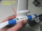
said in Part One, Mike Herrill from Excuform pulled for me a vacuformed copy of
the masters I made and he adapted for that purpose.
I am
not commercially associated with Him, I just gave him the basic masters and he
readied them to produce copies. I paid for my copy of the kit, I have no
monetary gain, nor participation in further commercialization. I just like to
see these obscure but remarkable planes come to light, as you all well know, and
in this case give the chance to experienced modelers to have their own too. If
Mike produces a copy for you, beware this is not actually your normal “kit”:
this “kit” has a minimalistic approach: no surface detail, no plans, no
interior, no accessories, no decals. It is just the shell of the shapes for
modelers to enhance it to the extent of their wishes or skills.
I
already posted here articles about two of Mike’s vacs, more or less a guide to
what you can expect from the Capelis (the Vultee V-1A and the Clark GA-43). But
for the Capelis you will have to get your own references (Part One of this
article mentions Skyways, the magazine that years ago published an article on
the Capelis. They sell back issues).
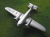
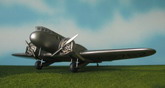
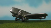
Click on
images below to see larger images
GENERALITIES
1) MARKING
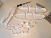
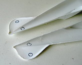
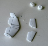
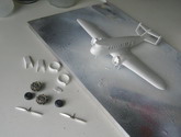
The parts’ separation lines on some vacs are sometimes not really well defined. This vac is not the exception for most of the parts. That’s one of the reasons you have to mark them.
Mark all the parts’ separation lines with a fine permanent marker. Use a ruler if you need to for straight sections. A pencil line is likely to be erased in the handling process, leaving you in darkness. Or in this case in whiteness.
Trace the demarcation line on BOTH sides of the part, inside –concave- and outside –convex-, as depicted. The line on the inside side of the part is very important because in most of the parts that’s where you should stop sanding, having reached the correct size of the part. If you feel adventurous apply your cutter on the concave side separation line, since that’s the real size of the part you need in this particular kit. If you want a margin of safety, use the convex side of the part separation line and then later on adjust sanding and comparing with your references. Don’t panic, look at the images.
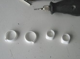
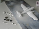
2) SCORING
Watch your fingers when you start scoring and cutting. Beware of the blade tendency to slip.
Put a new blade on your cutter. I mean really, a brand new one. I use an Xacto-type #11. Some modelers prefer curved blades, which makes sense. Therefore I never tried.
Whichever the side you have chosen to start scoring the parts, aim your cutter at an angle.
If you use the inside of the part reference line, aim almost horizontally pointing outwards.
If you use the outside of the part reference line proceed as usual, at a 45 degree angle.
You could use a continuous line or several partial lines that cross each other.
Hey, you already cut a number of parts. You know what? your new blade is not new anymore. PUT A NEW ONE.
The fuselage can only be scored and cut using the normal, outside separation line –the way you usually separate a vac kit part-.
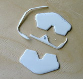
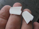
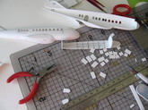
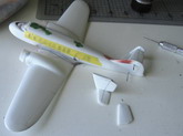
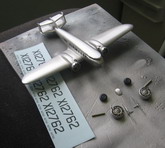
3) SEPARATING
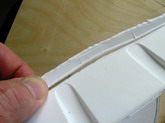
Once you have a decent score, may be after two or three passes, depending on the pressure exerted, the kind of blade, and the general alignment of the stars, start to bend the left over backing sheet back and forth until it snaps off (see images).
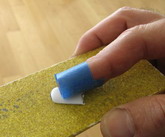
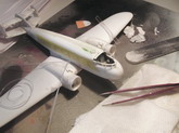
4) SANDING
Many parts will allow for a straightforward sanding on a FLAT surface. Proceed with patience, since here is where modelers find they overdo it. Your permanent marker lines are your reference. Check frequently, do not get carried away. Exert a uniform (spread-out along the part) pressure. If your fingers are in the middle of the stabilizer pushing down, that’s the area where you will remove most of the plastic, leaving the outer parts barely touched, so you end up with a banana part. You can wrap some masking tape sticky side-up around your finger to get some grip. Replace it when it gets contaminated with sawdust and looses the grip. I also use sometimes a ball of Blue-Tack or similar to get a grip at small parts.
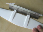
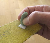
5) COMPLICATED SANDING
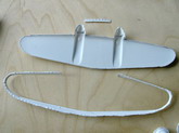
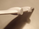
Some parts require special attention, like the fuselage halves. Sand uniformly. It is a common boo-boo again to sand too much in the middle and less at the nose and tail areas. Another usual occurrence is to leave the vertical stabilizer (part of the fuselage moldings in this case) too thick, as you concentrate on the fuselage
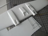
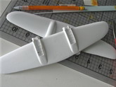
Wings are the other special parts. Here we have a slight dihedral in the lower surfaces. So you have to sand those areas (although it is one large part) separately (central panel, outer panels). Beware the engine nacelles. Adjust carefully when dry-fitting the wing halves.
6) ADJUSTING
If you have paired parts (stabilizer upper and lower parts, etc) start to check how you are doing, putting them together -as they should be eventually glued- and adjusting if needed.
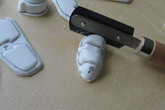
7) REFINING
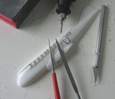
You see in the images the processes, tools and techniques used. Look at them. They are self-explanatory. Use progressively finer sanding tools, whichever ones you prefer. Pay attention to trailing edges, you may refine them by scrapping, filing, sanding (from the inside, preferably), whichever is your fancy, but they may need your attention.
8) DEVISING A STRATEGY
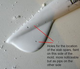
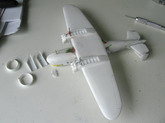
Plan a logical sequence for your build. For example, in this kit, both stabilizers on the biplane tail will have to be eventually separated in left and right halves. You will need to anchor them to the fuselage and fin in a safe and precise way, may be with spars (styrene rod or metal tube or wire), may be with styrene strip tongues. There are two minute marks on the INSIDE of the fuselage halves where those spars should be.
I first glued the vertical stabilizers to the separated lower horizontal stabs, then adjusted and glued the upper stabs to the fuselage fin via a spar and finally added those lower horizontal stabs –with their vertical stabilizers already glued as said- adjusting as needed (I needed to add a sliver of styrene to the inner part of the lower stabs.
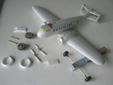
Want an interior? now is the time. Want a landing gear bay? now is the time. You will need engines, wheels, props, decals, etc. Start to think how to get them before you are too far on the building (for example, you may need to see how the engine fits inside the Townend ring). A contour gauge will be indispensable for making bulkheads and the like. They are not expensive. Go get one.
I had to cut an opening on the upper part of the central wing to allow for the interior floor attached to the fuselage.
9) BOO-BOOING
You cut too much. Big deal. Do not commit hara-kiri. Glue a piece of leftover styrene –you may have to remove a rectangular or squared portion to make the patch, or tidy the area -and let dry thoroughly. Cut again, but this time look at what you are doing, not at the TV show.
8) GLUING
I use Testors/Model Master liquid cement in general, the one with the fine metal applicator.
Sometimes I use cyanoacrylate. Sometimes I use MEK-like products, like TENAX.
Epoxy glues are occasionally used too.
SPECIFICITIES
There are several ways to do things. Use the ones that are more appropriate for you. Mine are just a general guide. You will see in the images of the building process some mistakes I made, a couple of them on purpose to show how to correct them. Again, this is not a kit for the neophyte. If you do some scratchbuilding and have dealt with a couple of vacs, you may have a go.
Check things as you proceed, pay attention while sanding, think twice before cutting, measure things when you need too, do not “eyeball”.
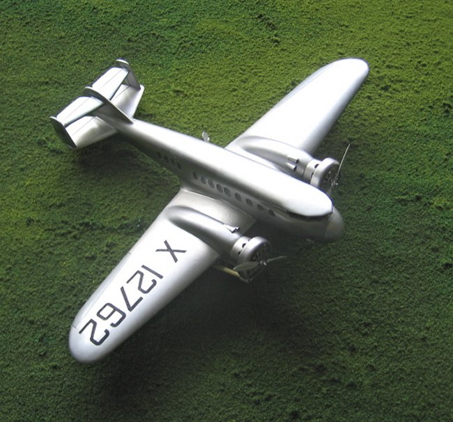
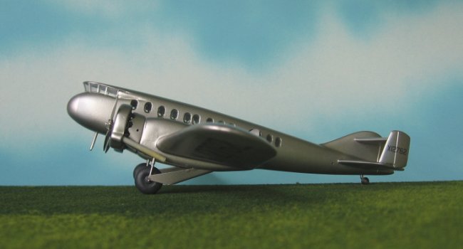
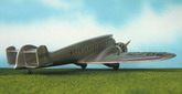
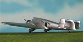
Little is known indeed about the Capelis interior, it is sort a mystery, and surely it changed over time and the different movies. To add to this mystery, the movies seem to have used the real deal for the exterior shots and some sort of studio prop for the interior shots, since they look far bigger than the real Capelis interior. The manufacturer stated that it could carry 12 passengers. There seems to be a windowed section aft the cabin door that could well have lodged a restroom and a galley.
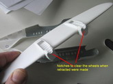
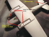
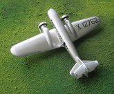
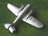
Beware that the tail wheel had different positions during the plane’s life: partially lodged inside the tail cone that was an integral part of the rudder (so described in the patents), and then moved later a bit ahead of that. It was described as retractable, and it could be retracted electrically or manually. I do not know if this is valid for both positions described before. The main landing gear fairings (sort of a flat pan shape) also suffered some minor transformations. The external “auxiliary” rudders had a strip added at some point to their trailing edges to increase their surface. Needless to say, the “movie” versions had the alternate nose –dispensing with the distinctive forward-leaning windshield and adopting a conventional canopy- and a couple of different window arrangements. Besides their “liveries” of course.
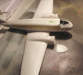
The Engines were Wright R-1750 Cyclones, with a small front shield and the exhaust collector surrounding it. I used for the sake of finishing the model a P&W Wasp I had around, the shield for which is bigger than the one above-mentioned, and coiled some solder around as guise of exhaust.
The cowling –not the Townend ring- immediately after the engine, connects with the engine gondola. There is a noticeable gap between the two (being the former bigger than the latter), which purpose seems to be to help with air circulation. There are a couple of air scoops per gondola. Look at their position in photos. There are some very fine lips at the trailing edge of the engine gondola as it blends with the wing. They are probably air vents and I depicted them on my model.
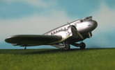
There are many ways to deal with the cockpit windows. You can paint them, decal them, or make them with transparent plastic. A simple way would be to cut the openings and install the glassing –perhaps while the fuselage sides are separated- and then mask them for protection. Another way –the one I did it- implies the removal of the cockpit roof, installation of the glassing, and adding a new roof. See images in the photo tutorial.
-The ailerons are described as being of the Frise type, therefore their chord will be bigger on the undersides of the wings than in the upper sides.
-There is a Venturi on the right side of the nose in the first version. There is an antenna on the lower fuselage more or less coinciding with the cockpit floor.
-No navigations lights could be spotted on the photos. There seem to be holes on the aft portion of the wing tips presumably for tie-downs.
-There is a hole on the fuselage immediately before the lower stab that could be to insert a lift bar. The cowlings immediately after the engines had holes too for the starter cranks.
-One of the movie versions had an antenna on top of the canopy and cables running from there. The movie versions had also a football antenna on the fuselage spine.
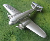
The “Five Came Back” plane was “Coast Air Lines” flagship, the “Silver Queen”. The “bomber” on the Flying Tigers” had a “CBAC” legend on the nose and above the door.
PHILOSOPHY:
You can build this model in many ways. You can paint the interior black or dark grey and be done with it. You can even use decals for the windows if you don’t want to cut them open –there are 24-, or tint the “glass” with a dark hue. Or you can speculate a bit and go for some interior; or go to town. It is up to you. Do as you wish. Same for the exterior detail. A basic approach could involve marking the separation lines for the ailerons and tail surfaces. I used masks to paint some panels using different metal hues, and so avoiding having to scribe panel lines.
I am looking forward to seeing a Capelis overcast over the skies of Model-Land.
Gabriel Stern
Click on
images below to see larger images
|
|