|
To say that I am a
fan of flying boats is like saying an ant likes picnics. They have a grace,
character and a utility that no other type of aircraft has, the ability to make
2/3’s of the world’s surface their runway. My appreciation for them was
fostered in part by my Dad, a licensed pilot from the “old school” of pilots
that learned to fly by the seat of their pants, and his ability for flying and
landing on water.
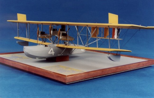
When
I first saw the story of the Curtiss NC series trip across the Atlantic in 1919,
the airplanes caught my attention. Immediately I knew I wanted to build a model
of one, and I knew it was going to end up being a scratchbuilt model. Even
though I have scratchbuilt a few aircraft before this, this was going to be the
first of this size and complexity. Gathering the reference data proved to be
fairly easy. A quick email to John Bayer, Director of the First Across
Organization, (http://www.geocities.com/firstacross/)
resulted in several sources of plans and reference materials. Another website
that gave invaluable information was The Naval Aviation History Office (http://www.history.navy.mil/branches/nc-4mono.htm).
I also thought a trip to Pensacola Naval Air Museum to photograph Nancy was in
order, so a quick email to the fine folks there to explain what I wanted to do
resulted in a very quick response. It
said in a nutshell, “Sure come on down, we’ll be glad to help.” A trip in
April of 2003 resulted in over 130 digital photos and 72 35mm Color Slides. The
people there were very accommodating. Not
only did they allow me full access to Nancy, but they also rolled out a small
electric scaffold to lift me up and over Nancy, allowing me to photograph the
airplane from the top, as well as the bottom. I was also able to poke my head
inside and get some very helpful interior pictures. I can’t recommend the
Naval Air Museum enough, very nice people to deal with and a fantastic array of
displays there.
With
references ready, and raw materials purchased, it was time to begin
construction. I decided to begin with some of the smaller subassemblies first to
get a feel if I was actually going to be able to finish this beast. The more I
looked at the plans, examined the forest of struts, the maze of rigging, the
more I started to think…
“
Riiiiiiiight. I’m really going to build this… sure I am.”
Along
with that, the drawings that I obtained from Model Airplane News had some
features that did not agree with the photos I had taken in a lot of areas. The
Nacelles weren’t drawn quite right, some of the rigging was mis-drawn, and
many details were left off the plans all together. Items like the wind driven
fuel pumps on the rear deck, and the “tunnel” underneath the rear pusher
engine to keep crewmembers from getting whacked by a spinning prop. Another
bugaboo that would bite me good later on in construction was the fact they were
drawn in two scales, 1/32nd and 1/48th. I was building the
model in 1/48th scale, so it wasn’t a major issue, but there were a
few times I had to get out the calculator to refigure a certain dimension.
Rather than go into a full-blown step by step construction article, I
decided to give a brief outline of each subassembly, and the materials and
techniques used to construct the model. That, and some In-Progress photos should
give you a good idea of the amount of work and time invested. As always if you
have any specific questions on how I did a certain part of the model, please
feel free to email me and ask away.
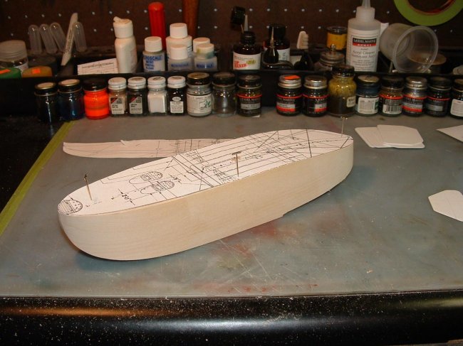
Fuselage/Hull
- Hull
master was carved from a block of basswood.
- Hull
halves vacuum-formed from .040 plastic sheet
- Internal
Hull stringers made from .010 and .005 strip.
- Ribs
and formers made from .030 sheet.
- Cockpit
floor and slat seats made from .040 plastic for frames and.010 strips for
slats.
- Instrument
Panel from .010 with Reheat Gages and Foto-Cut bezels
- Control
Wheels, Rudder Bars, Throttles and Engine Controls made from brass wire and
solder as needed, and spare photo etch.
- All
control cables present.
- Interior
finished to represent varnished mahogany.
- Cockpit
fairings vacuum-formed and faired in, with Compass and Windscreens made from
Rod and clear sheet.
- Hull
fittings made from brass or steel wire, solder, strips of plastic as needed.
- 4
wind driven Fuel Pumps made from Evergreen Channel and rod.
| Hull begins life
as paper templates pinned to the wood block and band sawed to shape, then
a small block plane was used to rough carve the hull to close to final
shape.
|
Click on
image below to see larger image
|

|
|
|
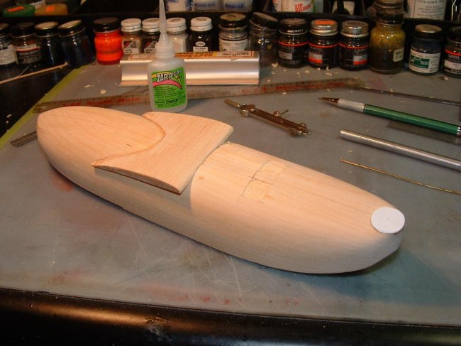
Hull
after final sanding and wing center section glued in place, and cockpit
cutouts chiseled out.
|
|
|
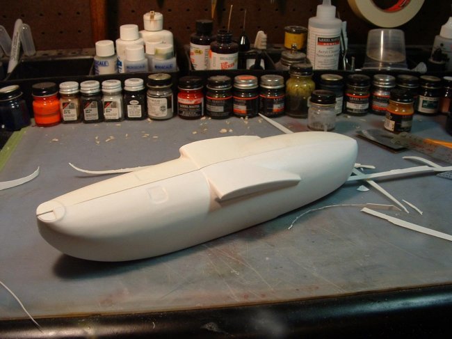
Hull
after vacu-forming. The basswood master was cut in half at the Cockpit
Bulkhead and left in the rear portion of the hull for strength. This
allowed for brass tube sockets for the lower wings to plug into. (and to
prevent me from being loony enough to build a second one)
|
|
|
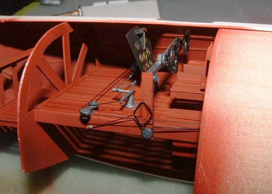
Hull interior showing slat
floors, Control Bar, Rudder Pedals and Slat Seats and all control cable
runs.
|
|
Wings
- Lower
Wing Center made from .040 ribs and brass tube spar, sheeted with .010
plastic with ribs embossed from underneath. Upper Wing Center Section
constructed of a 3/16 balsa core sanded to airfoil shape and sheeted with
.005 plastic, ribs embossed from below.
- Outer
wing panels, both top and bottom made from 3/16 Balsa core sanded to shape,
with 1/8 Rod embedded in wood at strut locations. Wings then sheeted with
embossed .005 plastic, Strut locating holes and rigging holes predrilled.
- Ailerons
cut from Top Wing panels, Aerodynamic mass balances added, and then sheeted
with embossed .005 plastic.
- Struts
made from Contrail Strut material, each strut cut and fitted as model sat in
jig. Ends pinned with brass wire, and each strut is embedded into the
plastic sockets installed in the wings. Epoxy was used to secure them.
| Lower Wing
structure, sans skins assembled and fitted. The assembly Jig is started.
|
Click on
image below to see larger image
|
 |
|
|
Clockwise
from top left. Wing skins
being test fitted. Ribs embossed from underneath.
Skins are being glued in place along lead edges. Skins being
cemented along outer ribs and trail edge and completed. |
|
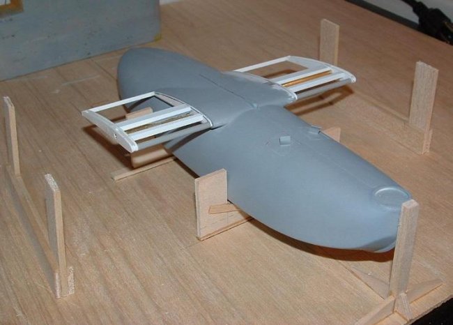
| Hull
completed, Painted, decaled and Lower Wing Center Section Completed. |
|
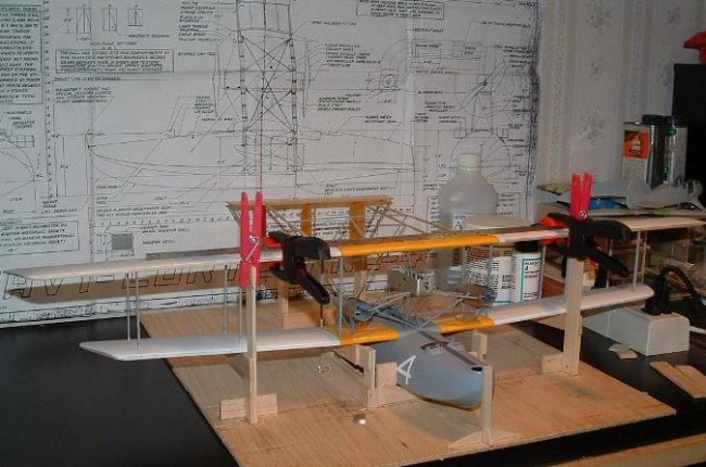
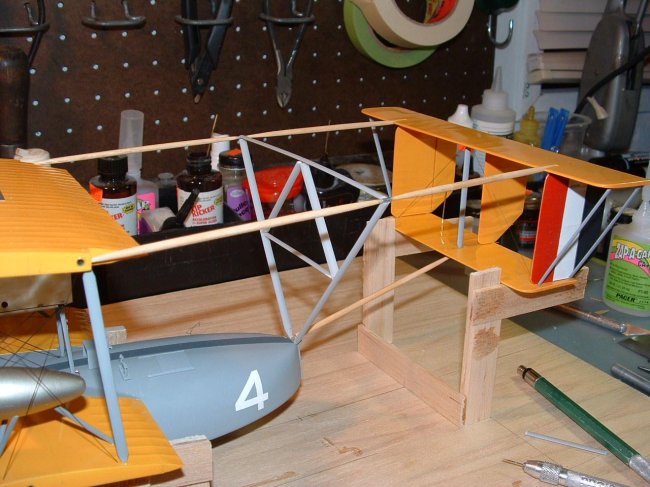
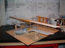
| Lower
Outer Wings temporarily set in place and Top Wing Center section jigged
into place. Balsa Cores with .005 sheeting was used for Wing construction.
Small white items under left wing are wind driven Fuel Pumps. |
|
|
Wing
Center Section Struts cut and fitted, Tail Booms started. |
|
| Top
Wing Outter Panels being test fitted
|
|
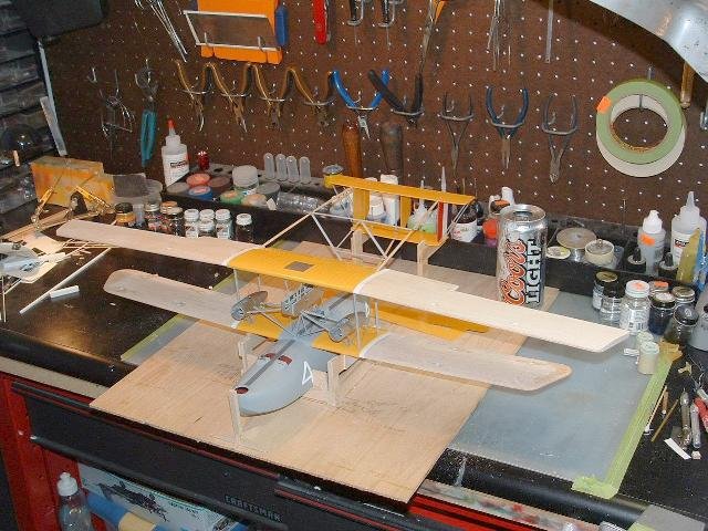
If
in doubt… Jig it. One of the most gratifying features about this model is that
in spite of the complexity of the construction, it all stayed in good alignment
because of the care and double-checking taken during construction to ensure
everything stayed straight. The jig was a bit of extra work, but the end results
were worth the effort. Here the Wing Struts are all cut to length, and numbered
for their particular location.
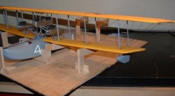
| Voila!
Removing the jig and nothing moved or “tweaked” out of alignment.
|
Click on
image below to see larger image
|
 |
|
Tail
Surfaces
- Both
Horizontal Stabilizers and all three Rudders and Fins made from .010 plastic
cores, sanded to shape, and skinned with .005 embossed plastic. All surfaces
were built separate and hinged with brass wire.
- Struts
made from Contrail Strut material, cut to length and anchored with brass
pins in ends.
- Assembly
was pre-assembled and painted, and rigged using Lycra thread, anchored in
pre-drilled holes with CA glue.
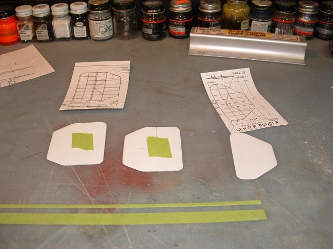
| Fin/Rudder Cores
made from .010 Sheet. |
Click on
image below to see larger image
|
 |
|
| Components test
fitted for fit and alignment. |
|
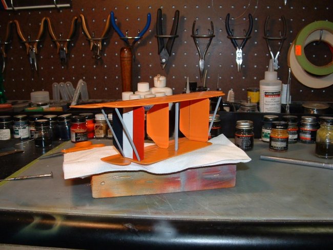
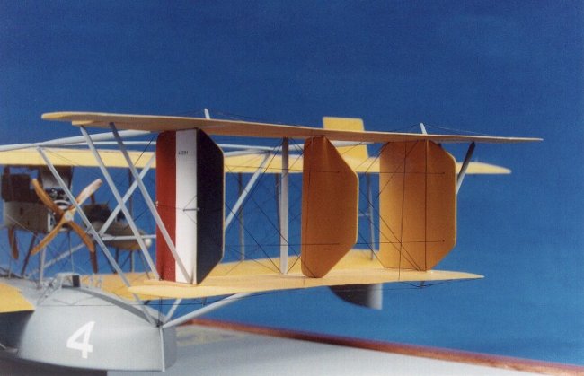
| Owwww my eyes!
My first attempt at “Yellowed NDL”
was woefully too orange. Testor’s Lemon Yellow was deemed adequately
close and Tail was repainted. Tail is complete here except for rigging. |
|
Engine
Nacelles
- Center
Nacelle built up from Evergreen Channel, internally rigged, and engine
bearers added from .060 plastic. Front Cowl and Lower Cowl Vacu-formed from
.010, side panels made from .005 plastic with foot and inspection cutouts
punched out. Nacelle Struts made from Contrail Struts, cut and fitted to
length in a jig.
- Wing
Nacelles vacuum-formed from .040 plastic over a wooden master turned on
lathe. Front cowls vacu-formed separately and added after engines were
installed. Radiators resin cast from a master made from a Chevy Pickup
Radiator, hoses are Solder Wire. Struts made from Contrail Strut material. A
special jig was made for strut locations and lengths, and for cutting and
fitting the Main Struts between all three nacelles.
- Engines
and propellers are commercial items. The Engines are Aeroclub white metal
engines, with separate exhaust stacks made from solder and drilled out.
Propellers are custom ordered props from Martin Digimyer and Copper State
Models.
|
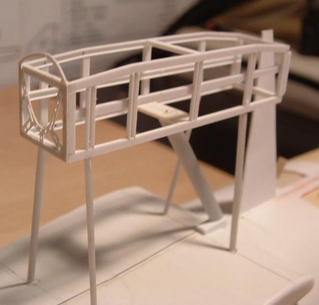
Center
Nacelle framed up with Evergreen. This was then covered with Vacu-formed
lower cowl and front cowl, and .005 sheet side panels. Large triangle
thingy in the front is an alignment aid. Struts are Contrail Strut pinned
with brass wire in the ends.
|
Click on
image below to see larger image
|
 |
|
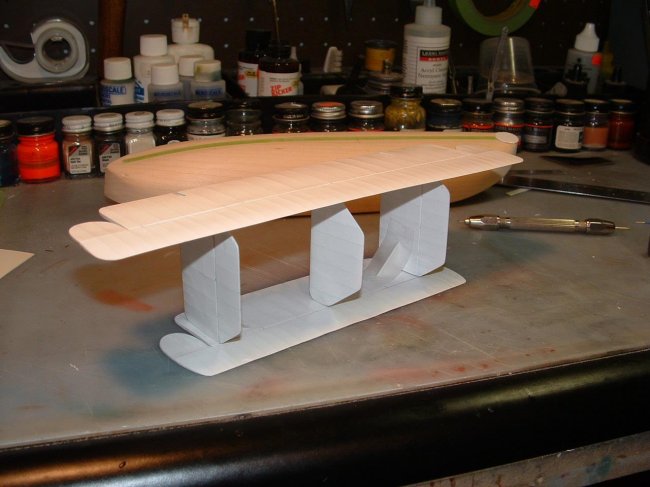
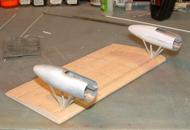
| Wing
Nacelles vacu-formed over wood master. A scrap piece of balsa was made to
the same size as the lower wing to make an assembly jig for cutting struts
to length.
|
|
|
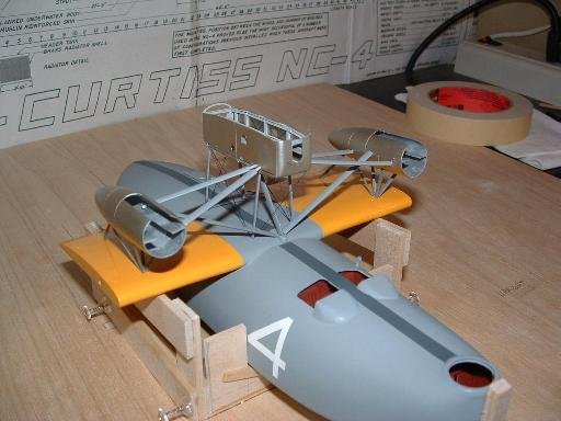
Nacelles
after being painted, and the forest of struts cut to fit. Cradle for
Assembly Jig helps hold everything in constant alignment to keep things
square and even.
|
|
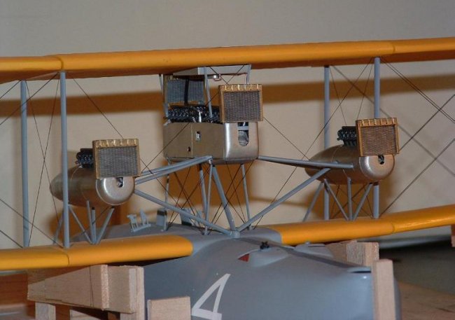
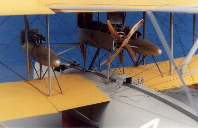
|
Engines and Radiators installed. Remember the comment on the two scales
being used in the plans? This is where it bit me good. I made masters to
cast the Engine Crankcases and the Cylinders. After casting 4 really nice
crankcases, and 50 really nice cylinders, it was then I discovered that I
made the crankcases in 1/48th scale, and the cylinders in 1/32nd
scale. As Homer Simpson would say… DOH! So I said to heck with it and
used the white metal Liberty’s from Aeroclub. They clean up nice and
look good when painted, and the props I had custom made by Martin Digimyer,
through Copper State Models.
|
|
Tail
Booms
- The
Main Booms are 1/8 inch dowel sanded to a taper on the ends. Center Fittings
are aluminum tube, drilled for Cross Tree and braces. Cross Tree made from
Contrail Strut Material, cut to length and pinned for strength. Center Tail
Boom also made from Dowel. All were painted with Gray Lacquer and epoxied
into place into holes predrilled in wings and tail.
|
Tail Booms being built. All were cut to length with the while model was firmly
held in place in jig. |
Click on
image below to see larger image
|
 |
|
Rigging
- Rigging
is a combination of Lycra thread used for wing bay and control line rigging,
and Nylon Monofilament used in the Tail Booms for strength. All holes
pre-drilled, and CA used to anchor lines in holes.
|
Lycra was used for Wing Bay and Control Line rigging, Monofilament was used for
the Tail Booms for strength and to hold it all in place |
Click on
image below to see larger image
|
 |
|
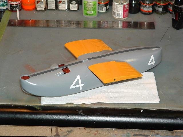
Painting and Decals
- Hull
painted with Gray Auto Acrylic Lacquer, with strips of white decal paper
used to form the Numeral 4 at all 5 locations.
- Wings
and Tail painted with Model Master Insignia Yellow, fin flash painted using
Insignia Red, White, and Blue, with Serial Number from scrap decals.
- Wing
National Insignia made using PC and Detail Master decal paper.
- Struts
and booms painted with Gray Auto Lacquer
Construction
- Nothing
unusual in construction once parts were fabricated. Epoxy and CA used almost
exclusively for strength and for filling seams. Wooden hull master was cut
at the forward bulkhead and left inside the assembled halves for strength. A
special jig was constructed to hold airframe in alignment as construction
progressed, and also serves as a transport caddy.
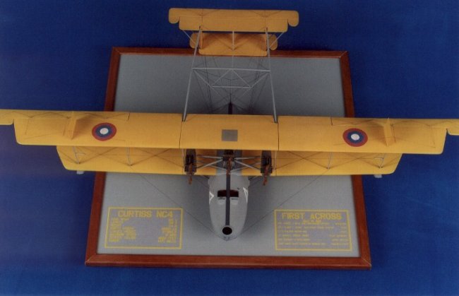
Finished base is ½ inch particleboard, sealed and painted with the
same gray used to finish model, and the pedestal is a block of mahogany.
Altogether about 734 hours were put into building the model.
This
was a rewarding project, in that I not only had a chance to exercise some
techniques I’ve used before, but I also had a chance to learn some new ones
along the way, talking to other modelers and seeking their input. Is this model
perfect? Heck no. I’ll be the first to admit it’s not… it has it’s share
of flaws and I know there’s a few places that I had to make some
“ejimicated” guesses due to lack of reference material, but over all I am
very pleased with the results. It never fails to draw it’s share of ooo’s
and ahhh’s wherever I take it, and it has won two awards so far, First place
in Scratchbuilt Class at BUFCON 25, and First Place in Scratchbuilt Class at
NOREASTCON 2004. It’s a unique
model of a unique subject, and I had a ball building it, which is after all,
what modeling is supposed to be.
I
want to give a special thanks to a couple of individuals who helped with the
model and the photography.
Fellow
club member Pete “Pig” Fleischman and his wonderful little vacu-form machine
did a great job in pulling the hull halves.
Another
club member, Tom Johnson did the great photography work.
Also
to everyone here at ARC for following along in the “In Progress” section for
their support and encouragement. It helped push me along at times when I was
ready to chuck the whole thing.
Cheers
Mike
|
|