|
I wrote an in-box
article for ARC on March 6 2004, about
Trumpeter’s new 1/35 Hind and I was all goo-goo eyed about it. The honeymoon
is over, and let’s say that this kit is great is most areas with the exception
of a few.
I do like the grey
plastic that it is molded in; it is soft and takes glue well. The detach point
between the edge of each part and the sprue is a bit large on most of the parts.
I use a precision pair or flush-cut wire nippers to remove parts, and they still
leave a large pock mark on every part. These marks required trimming and
filling. Perhaps it’s time for a new pair of nippers? 
A few problem areas:
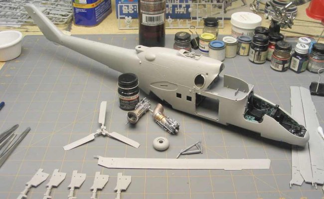
Engine
Bay
– Horrible ejector pin marks are located on the floor and vertical divider
between the engines. I puttied them and sanded well, primed, and painted. If not
taken care of, they should not show much after the engines are installed and
detailed with more plumbing and electrical.
Chin
Turret Housing
– A multi piece affair whereby nothing lines up, luckily it is the underside
that is a problem; some putty and white glue caulking necessary in one
particular area where the inboard half of the camera housing meets the underside
of the chin turret housing.
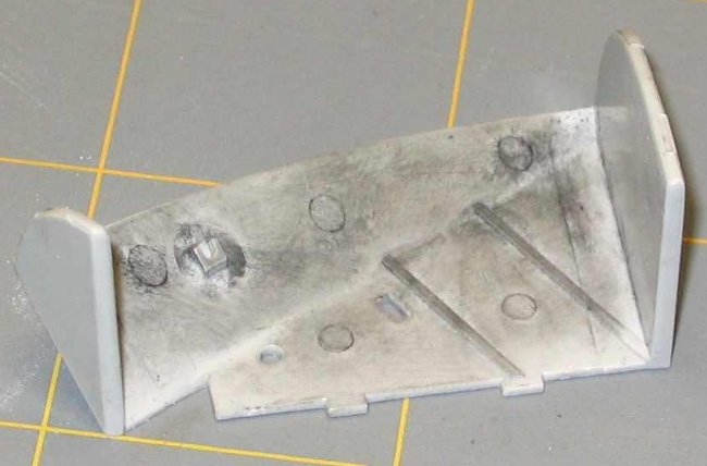
Main
Gear Bay
– More ejector pin marks. Get out the putty, but not too bad. It appears that
Trumpeter tried to do something with a few of them as they are scratched over
(raised) but not removed. I took a photo, shown later in this article, of the
raw part and hit it with some dry pastel to illustrate the unwanted detail.
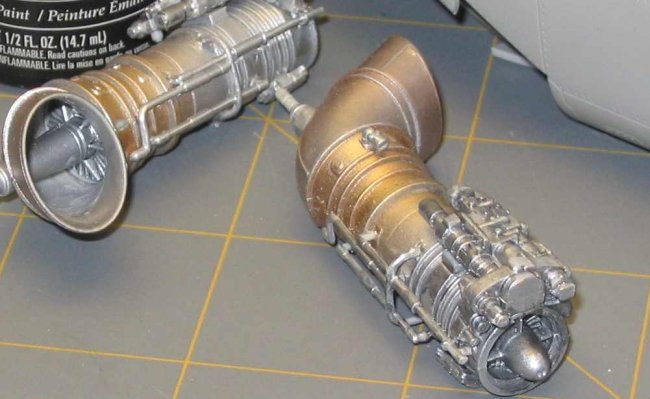
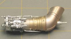
Engines
-- When finished, the turbines end up looking pretty good even after you botch
them like I did. Wet sand the glue surfaces of all engine halves on some fine
sand paper attached to a rigid, flat surface. This will flatten the gluing
surfaces and make the seams less noticeable. It will also remove the alignment
pins which are unnecessary as your eyeballs will do a better job of alignment of
these parts than the pins. Flat-sanding in this manner will remove all of that
added detail flashing that Trumpeter molded into the engine halves.
<< Special
Note for morons >> When I assembled
my engines, it was 2am. Do not do this. Make sure you are alert and not under
the influence of any drugs, as there is a port and starboard engine. The mistake I made was gluing
the port engine to the starboard exhaust and vice versa. Now all of the juicy
inboard engine detail (none) is facing outboard, and all outboard engine detail
is inboard, jammed up against that vertical bulkhead between each engine, where
it is not visible. (duh)
I guess I should
build it with the engine bays closed.
Clean all of the
flash from plumbing lines on engines; add plumbing last. In the end, plumbing
lines and accessories will cover up much of the seams on the engine halves on
the outboard sides of each turbine (unless you screw it up like I did). What are
the chances that there will be a Russian crew chief on the judging committee at
the next contest in Houston, Texas?
I painted the
engines in silver with touches of gold, copper, amber black and whatever other
colors gas turbines turn when they get hot. Then I washed the engines in a
thinned black wash of regular black paint to bring out the detail. Exhaust
turbines and drive shafts ARE visible from outside of the model via the large
exhaust ports (see photo), so I detailed them as well. The
interior exhaust tunnels on my model are not yet painted.
|
Click on
images below to see larger images
|
|
|

|

|
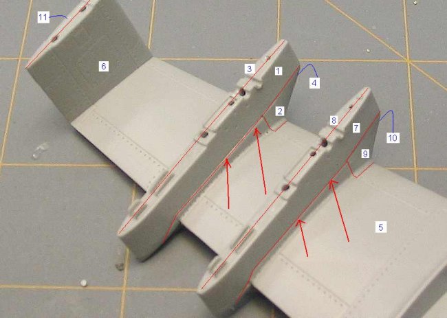
Stub
Wings
– The stub wing halves go together fairly well, but I am somewhat disappointed
in the fit of the parts in the wing section. This is the part of the model that
really was the big disappointment for me. Trumpeter has gone to great pains to
make this thing impossible to fit parts correctly in the weapons pylons. What
should have been 6 parts is more like about 12. I have attached a photo marked
up with part numbers in blue and parts bordered in red. The only parts you
cannot see is the top wing half (number 11) and the half of each leading edge
weapons pylon (number 4 and number 10). The thin red lines are joints between
parts, with bright red arrows indicating trouble areas. This wing is a joke.
Maybe some of you professionals out there can make it look better. Thank God
most of the problems are underneath the wing. The only thing I can think of is
that Trumpeter had to mold the parts this way to get the detail they wanted. Am
I making a mountain out of a mole hill? Maybe so.
Someone please make a set of resin replacement wings.
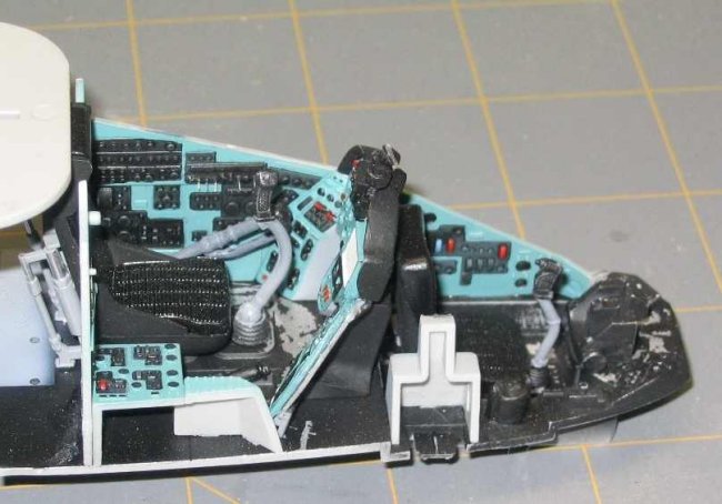
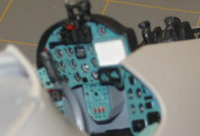
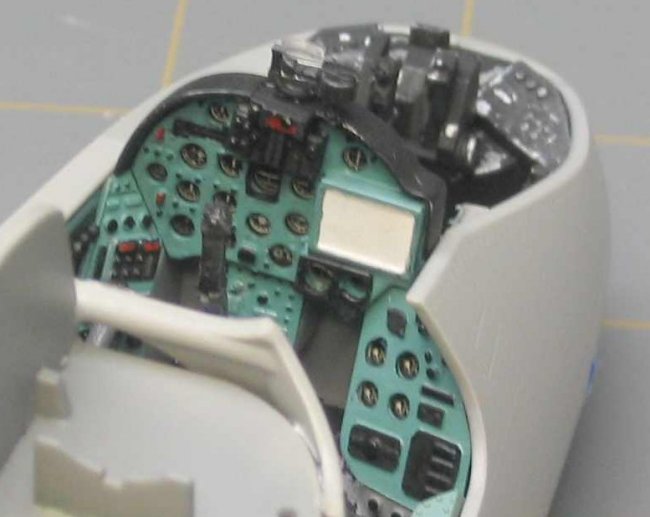
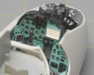
Cockpit
– Sand
the back off of the clear instrument panels so that the thickness is reduces by
50% or more. The clear panel is too thick, and acetate gauges appear to be
recessed 2” (scale) behind the panel. Overall fit of parts is good in the
cockpit area. Some of the side panels that contain gauges in the real aircraft
are merely a round circle embossed into the plastic panel with no decals or
raised lines provided as gauges, so you will have to create your own.
|
Click on
images below to see larger images
|
|

|

|
|
No aftermarket items
are available for this model as of yet (that I have seen), but someone needs to
make new tires (weighted), engine blocks, and stub wing sets, based on my
progress with this kit. Photo etch will be a must as well (Aries and Eduard, are
you ready?).
I will have more
photos and another article to follow in a week or so.
Jon
|