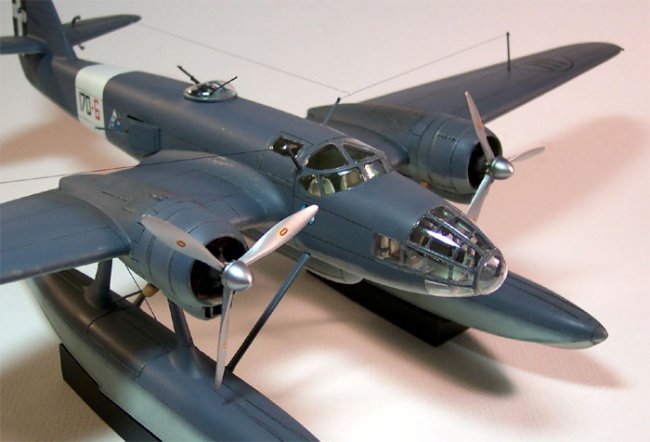
|
And so it begins, another large scale project. As with any models kit
prior to beginning construction the parts should be washed with warm soapy
water to remove any mold release agents or debris from the manufacturing
process. It is even more important that the parts be washed with a resin
kit, as the possibilities of heavier release agents being present are
great. I mixed a small amount of liquid dish soap in a large glass baking
pan with hot tap water, about 140 degrees Fahrenheit where I could swish
the parts and not worry about losing any small pieces. Each piece was
rinsed under cold water and set on a cotton towel to air-dry. That is
pretty much how day one of construction went. |
Click on
image below to see larger image
|
|
|
I
spent several hours carefully examining the parts and removing flash with a
razor knife, fine sand paper and diamond files. I removed casting blocks and
pour points off of the larger pieces and cleaned up all the connecting points.
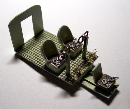
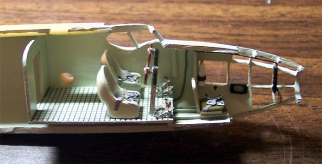
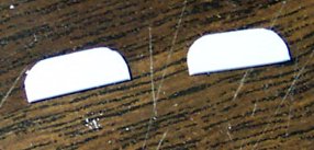
As with any conventional model, construction will begin with the interior. The
directions list four general color codes and for the interior that is “Sky”.
I coated the interior with a good coat of Testors primer gray then applied the
Polly Scale Sky. The cockpit floor pan, seats, control columns and waist gun
positions were done with Sky. The floor pan and completed seats were coated with
Future then washed with a sludge wash to highlight the details.
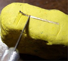
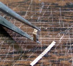
My reference book shows a chain drive system over the top of the control column
for the aileron control. Since this was a very visible item and would be easily
seen from outside the model I looked for ways to replicate it. Ultimately I
ended up cutting a thin piece of foil off my stock material, laying it over a
block of modeling clay and using a razor knife to make impressions into the
foil. This piece was then bent into a long “U” shape and super-glued over
the control column. I was careful to not apply a lot of pressure to the foil so
as to not remove the knife blade impressions. I painted this piece with
Gunze-Sangyo Burnt Iron.
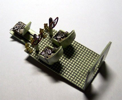
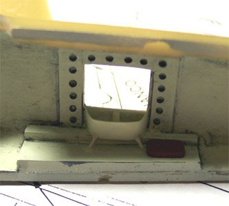
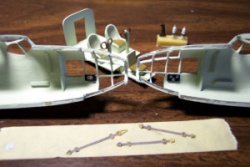
As the kit interior is very plain I started
to collect some detail parts to make it a little more “busy”. I still had
some brass seat belt buckles left over from the Koster Fw-200 so those were
combined with some foil strips to make seat belts. Considering the time period
and type of aircraft I just made lap belts, no shoulder harnesses. From the
parts box I found some leftover brass rudder pedals that came with the Fw-189
and was lucky enough to come up with four to complete the pilots and co-pilot
position. I used some short lengths of fuse wire to make the posts for the
rudder pedals.
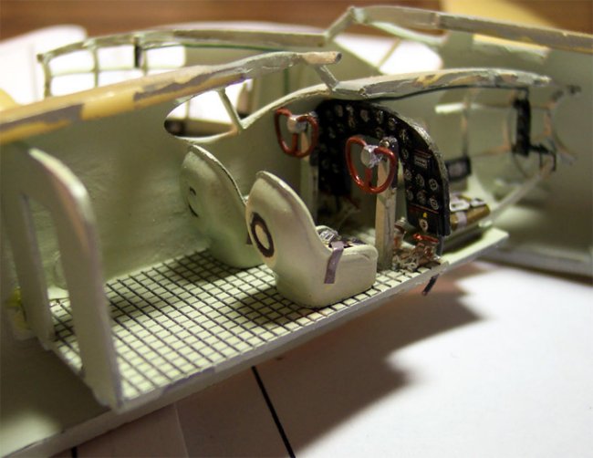
The instrument panel is the next area to get some attention. I really like to
bring instrument panels to life. This panel is painted sky on the backside and
flat black on the front. The instrument faces were done with flat white then
Reheat instrument faces were applied with a liberal dose of Micro-Sol setting
solution. There are three small panels that go in the nose for the bombardier
station and they got the same treatment. The side panels in the nose have no
detail cast into them at all so I painted the faces white then used some of the
larger square decals from Reheat. After the Micro-Sol had dried I touched up the
edges with some flat black on a fine brush.
Continuing with my mission to dress up the cockpit I am using a selection of
fuse wire pieces painted in various shades of dark gray to make umbilical
cables. The first cable will run from the front side bombardier’s consol along
an overhead beam and into the body of the plane. The pictures I’ve found show
a complex bombsite that I will replace with a spare PE bombsite from that
leftover Fw-189 sheet. This I attached to the front bombardiers consol in a
similar position to the one in the reference picture. More fuse wire is used
along the sidewalls in the nose. Using more scrap brass and some plastic sheet
stock I constructed a small instrument panel to mount above the bombardier’s
position per the reference photos. Another thin piece of fuse wire runs from
this panel into the body of the plane. Another heavier piece is set onto the
backside of the main dash and fed under the floor pan. A few more odd PE parts
are attached to the side of the bombardier’s seat slide as release or
adjustment levers and the dress up program is complete.
The cockpit assembly was super-glued in place by laying a good bead of glue
along the interior alignment tabs, holding the assembly in place while putting a
drop of accelerator onto the bead. The halves were dry fit immediately to be
sure everything was lining up properly then additional glue was applied to the
back wall area of the cockpit. I test fit the dash to find that my rudder pedal
addition was going to cause some trouble. I had to trim the bottom edge of the
dash just slightly to get it to clear the tops of the rudder pedals then it was
super-glued in place. Again the fuselage was dry fit to make sure there was no
binding going on. So far all the pieces are fitting very nicely and looking into
the front window areas the craft has a nice, busy look to it.
To quickly sum up the additions to the interior we have:
1.
Simulated chain on control columns.
2. Foil seat belts with brass buckles
from spares box.
3. Reheat instrument faces on all
panels and dash.
4. PE rudder pedals from spares box.
5. PE bombsite from spares box.
6. Scratch built secondary bombardiers
panel.
7. Fuse wire umbilical cables added in
various areas.
Continuing with typical construction methodology I’m moving on to the waist
gun positions. I am not happy at all with what the kit offers here. The kit gun
tubs are rectangular with both long sides bowed in whereas the actual gun tubs
were more rounded, mounted flush to the exterior wall of the fuselage and had
two small support legs. The armature that the kit provides to support the gun
appears accurate. At first I thought I might try to salvage the kit gun tubs but
have decided that I will be way ahead of the game to simply scratch build them.
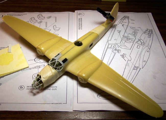
I don’t feel like doing that today so I will take a look at the wing
connections instead.
I learned my lesson with the S-38 and super gluing large pieces. It may be just
fine for sticking the little things together but when it comes to the big stuff
you’ve got to go with the epoxy. I’m using Loctite five-minute epoxy to
attach the wings. A couple of fit problems are coming to light right away along
with a larger problem. First, there is a small step on the top of the Port wing
and I’m trying to adjust for it by sanding a small amount off the tops of the
mounting pegs. I’m also sanding the top of the fuselage joint lightly to try
and blend the seam in. The bigger problem is the wing size itself. The entire
wing is about 3 millimeter narrow overall. There is a step back at both the
front and the back of the wing to the fuselage and to make matters even worse,
the end of the flap carries onto the fuselage part of the wing root and the
panel lines do not meet, not even close and this is apparent on both wings.
I’m going to have to shave the fuselage to meet the wing, fill the panel lines
and rescribe them.
The directions show the fuselage being assembled then the wings going on. From
the earlier interior pictures you can see that there is an alignment/mounting
stub on each side that will protrude into the cabin area and be visible from the
outside when completed. The prospect of covering this up with dental tools
through the cockpit windows is not very appealing. I taped the fuselage together
securely and test fit the wing to check how the dihedral would set up and was
pretty happy with it and this prompted me to attach the wing first, clean up the
interior area then close the fuselage, hope this approach works because I used a
bunch of epoxy to attach those wings. I also cut a little off each of the
forward mounting stubs to facilitate the final clean-up. Although the epoxy set
up well it did remain soft for a while so I set the entire assembly aside to
cure overnight and will start sanding tomorrow. I’m going to have to get back
to those gun tubs shortly also.
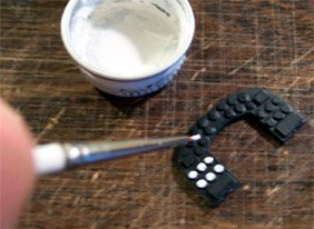
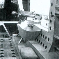
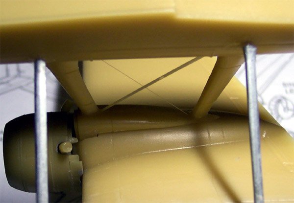
To rectify the gun tub situation I am using
a selection of Evergreen plastic strips and rod. I’ve measured the general
length and width of the area I want the tub to cover and cut out rectangular
pieces of heavier strip for the flooring. The two outside corners were filed
down then thin strip was bent around them and glued to the edge. Using my sprue
cutters I cut the strip off at an approximate angle then inserted the tub into
the fuselage to correct the angle.
|
I glued a piece of styrene rod to the tub floor with Tenex 7R then leaned
it over to the correct angle with the fuselage wall while the glue was
still setting. The excess rod was cut off flush with the bottom of the
gunner’s window. The gun and gun armature will be mounted after the
model is painted. The gunner’s cushion is formed from some heavier
Evergreen strip with the hard edges and corners filed off. At this point I
was considering just how much interior detail work I really wanted to do
so I closed the fuselage and looked through the windows. From what I could
see just about anything additional that I did would be hidden upon
completion. The gun tubs and cushions were painted and super-glued in
place. The short support legs were fashioned from heavy fuse wire. |
Click on
image below to see larger image
|
 |
|
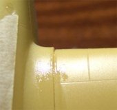
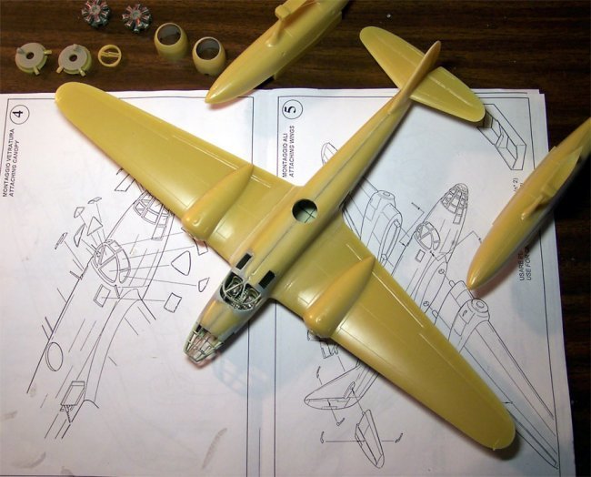
Now I’m moving back to the pesky wing fit problem. The trailing edge was
fairly easy to deal with by just shaving it down with a razor and thinning the
new trailing edge a bit to match the wing. The forward area was much thicker and
required some judicious work with a Dremel and teardrop grinding stone. Once the
majority of the excess material was removed I shifted over to medium grit
sandpaper then a fine sandpaper to finish it off. The lower flap lines needed to
be filled with superglue and re-scribed but we’re only talking about less than
a half an inch of line on each side so it’s not that bad. I’m also starting
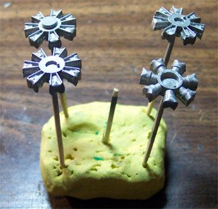
to work on the engines. Each bank of cylinders gets mounted on a toothpick for
handling and painted a base coat of Model Master Steel. I added ignition
harnesses from fine red fuse wire and assembled the engines per the
instructions. The interiors of the nacelles and the front and back of the
mounting plate were painted RLM 02. The engines will be sludge washed and put
aside for later attachment.
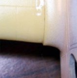
It’s time to close the fuselage
permanently. I’ve run a good bead of epoxy around the edges of the fuselage
except for the window framing in the nose. This I will secure later. The
fuselage halves were lined up and wrapped with masking tape and small clamps.
Pressure was applied to a few strategic areas to help things line up properly
and five minutes later the epoxy had set. The window frames in the nose were now
lined up by gently flexing them with tweezers and super-glueing them into place.
The elevators were attached with super-glue and accelerator. The main seam was
first cleaned with a razor then sanded and looked pretty good with very little
work. There are still a few small seam areas that need more attention but it is
coming along rather nicely.
|
Click on
images below to see larger images
|
 |
 |
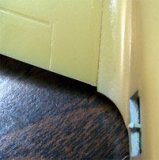
| I set the model
on my work surface and aligned the rudder perpendicular to the table then
measured the wing tips for dihedral - right on the money! |
Click on
image below to see larger image
|
 |
|
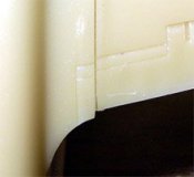
I spent nearly an entire evening going over the seams carefully cleaning them up
with a razor knife and various grades of sandpaper. Finally, satisfied with that
part of the job I can now turn my attention to the floats. In the reference
pictures there are two things very visible; first is a fine cable that runs in
the opposite direction of the cast support cable and second are short rudder
control cables. For the main float cable I simply drilled through the
top-mounting pad and threaded a piece of invisible thread into it. One end was
secured to the top of the float with super-glue then, while putting some tension
on the thread the other end was glued. The rudder cables will be short pieces of
fuse wire.
After the floats were tested for fit I had to
sand the contact point of one just a little then applied a good layer of
super-glue into the contact point and set it in place. I ran a drop of
accelerator into the joint and the placed the second float in the same manner. I
was a little concerned about the weight of this model on the float legs until I
took a good, close look at the white metal struts. Usually when we talk about
white metal parts we’re thinking of soft pewter but these struts are actually
made from pot metal and are very hard. If I had really been paying attention I
would have drilled out the mounting points for the struts but I was not paying
attention. Rather than try to drill these large holes now that the model is
nearly complete I simply cut off the tabs from the struts and glued them in
place. I carefully worked some glue around the connecting points with a dental
pick and set it with accelerator. This blended the contact points in nicely. One
needs to be careful here, the struts are of two different sizes; the sort ones
are for the front while the long ones are for the rear. I of course installed
both long struts in front then was wondering why the heck the rear struts were
so short. Fortunately the super-glue had not set up completely and I was able to
break the struts free and start over again. The armament tub was glued on at
this point also.
Matt
|