It’s
big, it’s expensive it’s fantastic. It comes in a box full to the brim on
nineteen sprue frames and a few odd bits, there are metal inserts for the
undercarriage and a choice of rubber or plastic tyres for the wheels not
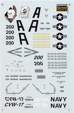
forgetting the screws and screwdriver. Along with this comes a giant decal
sheet plus a second smaller sheet with markings for all the stores. There is
so much to do that it takes a forty-page instruction booklet to handle it all.
The kit parts are nicely presented in the box with a clear view cover and
separate box for the loose parts. The plastic mouldings are of the highest
quality with engraved panel lines and the fit is excellent with the exception
of the two intake lips.
|
The kit build starts at the cockpit as usual an it is pretty obvious that
there is going to be a two seater produced at some time as the tub has two
places and there are two seats but the second is covered by the solid rear
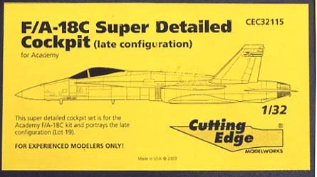
decking. I decided on the Cutting Edge update set with its one place tub
and open rear decking. |
| This is a work of art with separate centre console,
individual rudder pedals, HUD unit and instrument coaming plus clear resin
instrument panel, the seat is very nicely detailed with seat belts looking
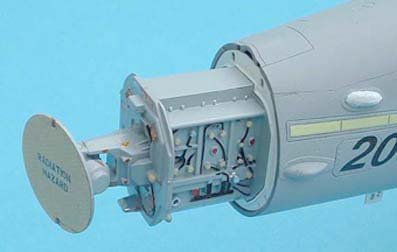
quite realistic. New side walls are provided for the cockpit and the equipment
bay comes as a separate section with several boxes to place inside, a nice
touch is the fine wire mesh supplied to cover the bay with along with a
pattern for cutting to size. The one thing I liked about this set was the fact
that there was very little sanding to be done to remove pouring blocks, the
tub needed light cuts along the side and the equipment bay needed none at all. |
|
|
|
The seat needed a
razor saw cut and the instrument panels only needed the holes clearing the
rest were cut off tiny mounts on the main
blocks
A new canopy frame is provided to
replace the kit item, which only goes half way along the bottom edges and
meets a moulded on section, this is to be removed before adding the new frame,
it can be done at the same time as you remove the centre mould line along the
canopy and wind shield. I just sanded the line off with fine wet and dry paper
then sanded the area with a worn out piece of 1200 grade paper before
polishing with canopy polish. |
The
undercarriage is a true replica of the real thing, I think every part on the
real legs has been reproduced in plastic and these encase the metal inserts to
take the weight of such a large model, I was so impressed with these I made
them up first and it took me two full days to do three legs. Note the separate anchor
shackles
Construction notes
Step
3 The nose wheel bay comes as separate pieces, walls and roof etc. etc. these
are worth painting before assembly as there is so much detail there and colour
notes are provided in the step.
A tip
here, the colour list is on the back page so I photocopied it
and hung it up in front of me to save keep turning the sheet
over.
Step 4
Check the insides of parts G 47/48 for ejector pin marks, as these will
interfere with the fit around the metal leg.
Step 5 You must fit the nose gear in at
this step as the fuselage halves prohibit it
later.
Step
9 This is where you must make up your mind if you want folded
wings or not, care must be taken with the cuts but there is no need to add the
outer panels until much later in the construction. I have heard that there are
problems with this configuration but I have seen it done without problems and
I could not foresee any myself.
Step 11 this is where there really is a
problem, the intake lips parts B 31/32 do not want to fit flush with the sides
of the outer walls I had to use filler and some sanding to blend them in,
several modellers have reported the same problem but one guy says the answer
is to fit the intakes first then add the side walls parts A3/4 from step 9
afterwards.
Step
12 The leading edge extensions were added here and I added the
upper and lower nose sections parts E 13/14 from step 20, part J 15 is placed
in position but not cemented and the whole section was held together with an
elastic band to maintain the correct cross
section.
At this stage I cleaned up all the fuselage
joins before thinking about any further
additions.
Step
14/15 decide which angle you want your flaps set at and add the
appropriate hinges, check alignment using the flaps themselves but don’t
cement them, leave overnight to harden. Take care to get the slats on the
correct side, they can be confused.
Step 16 Even if you are not folding the wings you
need to make the cuts in parts E 5/6 to give the correct look. When
assembled
Step 21Radar time now, there is a good
replica of the real unit which will slide in and out, if you wish to show it
off I would suggest that you leave it all off until late in the construction
as with such a large model it can easily get
damaged.
Step
22/23 Some of the tiny linkages on the main gear are a tight
fit but don’t force them as they really are tiny and could easily break just
add a touch of liquid cement and they will slip in a lot easier, parts J 31/32
have a small location on the bottom end, make sure you don’t cut this off
thinking it is a moulding tab. I suggest you make one leg at a time as some of
the linkages are handed and could be placed wrongly. The main gear can be
fitted without cementing and I removed mine while I sprayed the whole model
using the gear doors held in place with a blob of BluTack as masks for the
bays.
| Step 31 I
wanted my canopy open to show the cockpit at it’s best but the kit lifting ram
part J 52 seems a little weak so I cut it off and replaced it with a cut down
pin, not quite the correct shape but it will stand the test of a few
knocks. Note the folded back cover on the equipment bay,
this is not unusual on the deck but would be closed for
flight. |
|
|
|
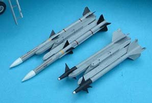
That’s about all the construction problems I found
and the remainder is a simply boring job making up tons of weaponry very
little of which you can use at one time, there are four large frames of bombs,
missiles, launchers and pylons for you to make up any conceivable load for the
Hornet. I made up just a couple of each item just to show around. At the end
of the day I filled the small box that the metal parts came in with leftovers
from missiles etc. etc. and two seater
parts. |
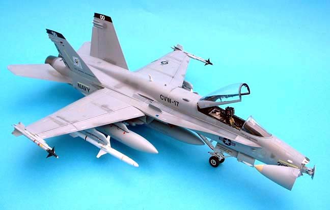
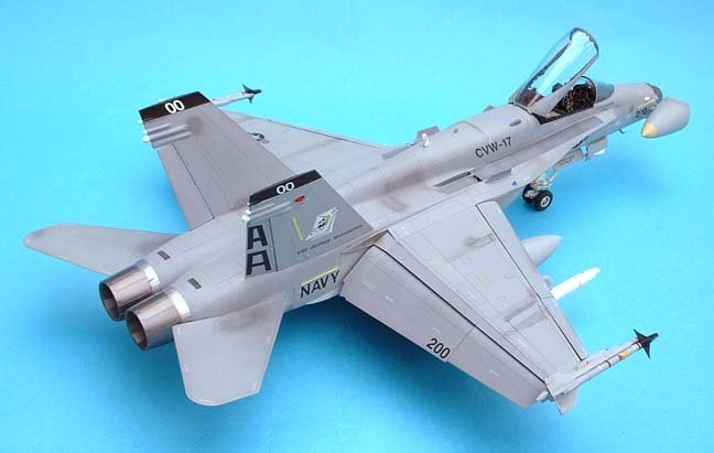
Painting and
decorating, there are only two
shades of grey on this bird and many brands of paint carry these in their
range, I personally used the Humbrol “authentics” tins I had, after leaving
for a day to harden I dusted two coats of ”Klear” and then a good glossy
coat.
The decals supplied by Cutting Edge give the
essentials for Capt Dana Potts aircraft but you need to use the Kit sheet for
the data stencils, one point here the formation lights along the fuselage and
fin are supplied as separate pieces with raised edges representing the frames,
now the kit decals are tailored to fit these where as C.E. decals are a
fraction too long and will not lay down in the recess.
| A fresh coat of Klear now seals the decals in and a mix of
three parts Klear and one part Tamiya flat base was dusted over to bring the
whole model back to a low sheen.
I did some weathering but not much as this is
a CAG bird and the photos I have of it show quite a clean
machine. |
|
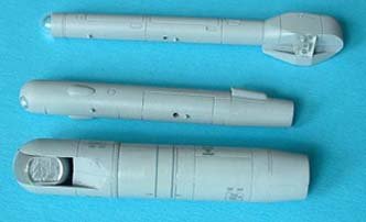
Now is the time to add
all those extras such as nose cone and radar if displayed open, missiles, fuel
tanks and cockpit furniture oh and don’t forget the wheels, you have a choice
of tyres, rubber or plastic, I chose plastic as I heard that the rubber tends
to rot the plastic after a while.
|
|
When it comes to engine exhausts you have a choice of four sets,
open or closed petals with appropriate inner petals and there are different
petals for early and late engines, I chose the later ones and coated them with
Alclad II steel.
Four figures are included in the
kit, two pilot figures in different poses and two ground crew again in
differing poses, this pair have decals for various operations on deck on the
sheet, I have put them together but I am no figure painter and so they remain
in the box for now. |
It’s big, it’s expensive
it’s fantastic, but I like it. If you have the room for it go for it you won’t
be sorry.
Ted
Drop by Ted's
Website to see more of his models. Ted
Taylor's Modelworks